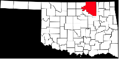
 Osage County is north of Tulsa, Oklahoma and has a rich history in the oil industry. Men like Philips and Sinclair became legends there, and also very wealthy. They drilled and produced the oil that fueled the engines of industry.
–
–
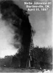 Oil has been produced in Osage county for over a century. The Nellie Johnston #1 was one of the first commercial wells from 1897 as can be seen from the image on the right. Through the first half of the 20th century oceans of oil were produced in the area, however today, most of those fields are played out. There is still oil to be found, and stripper wells continue to produce oil today.
–
–
–
–
–
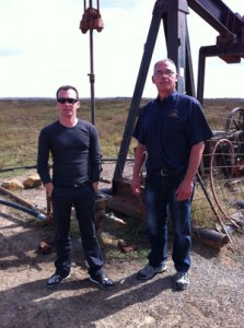 My guide for the day was James Revard, Executive Director of the Oklahoma Marginal Well Commission (OMWC). We were joined by Rick Torix, the OMWC Education Coordinator. In the picture on the right, Jim is on the right and Rick is on the left. It was another beautiful day to be out in the field.
Through the day, we stopped at wells next to the roadway and looked at the different types of well configurations. Most were oil producing, however one installation was gas producing.
–
–
–
First Site
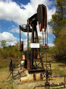 The first well we came across had obviously been in service a number of years. It was typical of many sites I have seen. The location information was posted on the front of the pump jack. The system was powered by a small electric motor.
There was a small fence surrounding the pump jack, which appears to be in need of repair. Jim Revard said that curious cattle, and even kids are attracted to the equipment. Unfortunately, their curiosity can sometimes be fatal.
In many cases I noticed that the wellhead is not fenced, however it is still important to be aware of the moving parts.
–
–
–
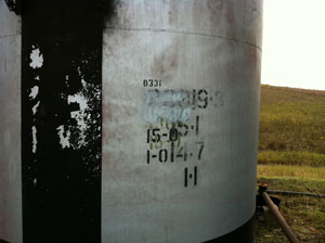 There were two oil tanks and a separator at the tank battery. I noticed that the identifying numbers on the two oil tanks had been modified several times. According to Jim, the lease has probably changed hands a number of times, and each owner had his own tank code.
–
–
–
–
Second Site
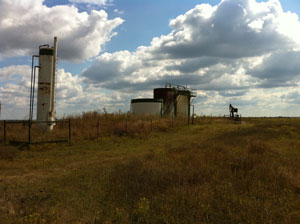 The next site we visited produced both oil and gas, and the gas was used to power the pump. The tank battery in the picture is fenced and it appears that the grass inside the fence is never cut.
Two wells were visible from the tank battery. One is visible in the image on the right.
–
–
–
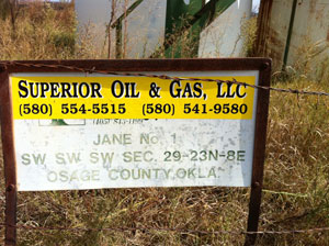 The location, using the township method, of the tank battery is posted next to the fence. Interestingly, on the wells we visited, I never saw latitude and longitude used on the signs.
–
–
–
–
–
–
–
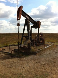 If you think that the pump jack in the picture on the right looks like it is in a state of disrepair, that’s because it is. It was unclear how long it had been sitting idle, but it turned out to be a good opportunity for Jim to explain how a natural gas engine works.
–
–
–
–
–
–
–
–
Third Site
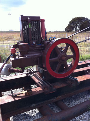
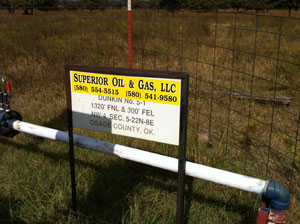
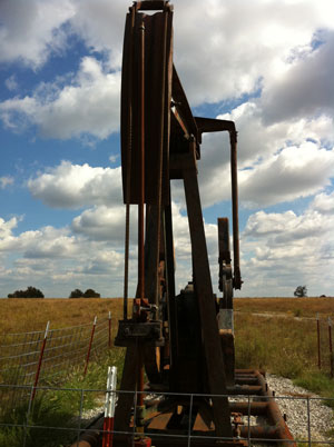 The next site featured another gas driven pump as seen in the photos on the right. The location sign in te next picture looks fairly standard. This pump jack also has a sturdy fence surrounding it.
–
–
–
–
–
–
–
–
–
–
–
–
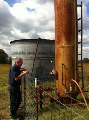
The big difference with this site is the absence of oil storage tanks. As you can see from the picture on the right, there is a separator and a saltwater tank. This indicates that this well is a gas producer and that the pump is used to keep the water level in the well low enough to allow the gas to escape from the producing formation.
–
–
–
–
–
–
–
–
–
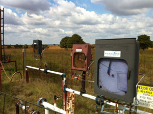 Jim pointed out that the three meters in this picture indicated that there were, in fact, three gas wells coming into this one site.
–
–
–
–
–
–
–
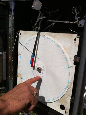
We took a close look at one of the recorders. It features a circular chart that covers approximately one month of data. In order to monitor gas production, two channels of data are recorded, one red and the other in blue. You can see the red and blue pens in the picture.
Once the gas is metered on-site, it is shipped via pipeline to a processing facility.
–
–
–
–
–
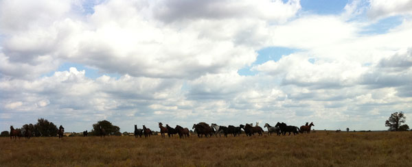
One of the benefits of working in the field is the opportunity to see beautiful sites, such as the herd of horses in the picture below that came to take a look at us as we were walking back to the car.
–
–
–
–
–
–
–
–
–
–
–
Fourth Site
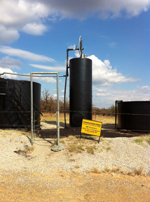 The tank battery for the next site is shown on the right. The yellow location sign is prominently featured.
–
–
–
–
–
–
–
–
–
–
–
–

As you can see from the next picture on the right, the ground around the tank battery was heavily soaked with oil. You can see a pit in the foreground filled with fluid.
–
–
–
–
–
–
–
–
–
–
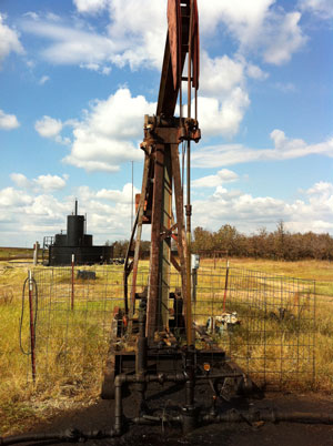 The pump jack was located a short distance from the tank battery. The ground around it was also oil soaked. A simple wire fence surrounds the pump jack.
–
–
–
–
–
–
–
–
–
–
–
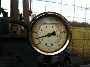
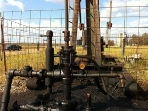 The wellhead assembly is typical of what I have seen. The pressure gauge caught my attention. As the pump goes through its cycle, the pressure gauge moves from zero to about 18 psi and back, indicating fluid is moving.
–
–
–
–
 –
–
–
–
–
–
–
–
–
–
–
–
–
Summary
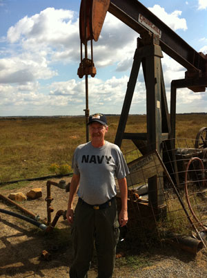
In general, the sites we visited were not cared for as well as others I’ve seen. Grass was overgrown, berms needed attention, water tanks didn’t have net coverings and there were some spills that needed to be cleaned up.
Some of the things I need to work on are perhaps gas production charts, and how to display them on the iPhone. The ability to document the condition of a site with pictures keeps coming to mind. This could be coupled with checklists for spill prevention compliance and maintenance purposes.
Somehow these old wells keep producing year after year. My hope is that tools like the iPhone software under development will help pumpers become more efficient and productive.

Recent Comments